

เหตุใดการตรวจสอบแหล่งกำเนิดแสงจึงมีความสำคัญในการทดสอบโมดูลกล้องสมาร์ทโฟน
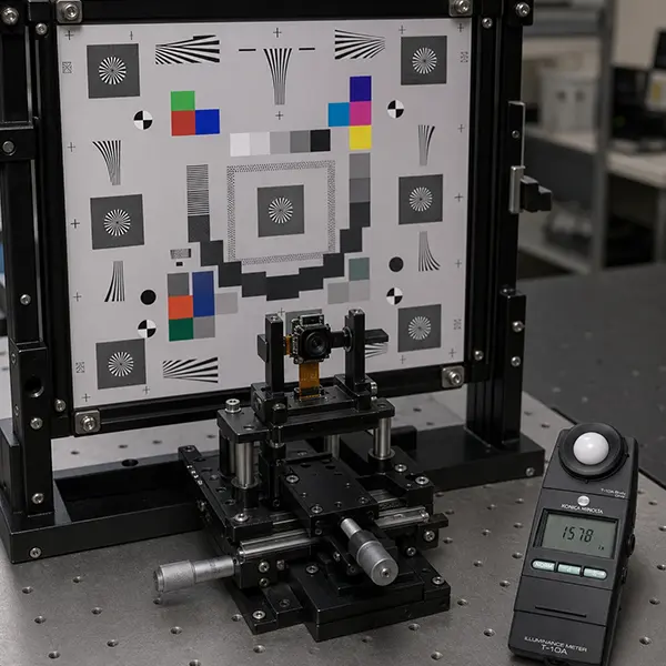
โดยทั่วไปแล้ว โมดูลกล้องของสมาร์ทโฟนจะผ่านการทดสอบทางแสงก่อนการประกอบขั้นสุดท้าย ขึ้นอยู่กับกระบวนการผลิต ซึ่งการทดสอบเหล่านี้อาจประเมินค่าฟังก์ชันการถ่ายโอนการมอดูเลชั่น (MTF) การบิดเบี้ยว ความสว่างสัมพัทธ์ เฉดสี สมดุลแสงขาว และการตอบสนองของสี
ความแม่นยำของผลลัพธ์เหล่านี้ขึ้นไม่ได้ขึ้นอยู่กับโมดูลกล้อง แต่ยังขึ้นอยู่กับแหล่งกำเนิดแสงของการทดสอบด้วย หากแสงสว่างไม่เสถียร ไม่สม่ำเสมอ หรือมีสเปกตรัมไม่สอดคล้องกัน อาจทำให้เกิดความแปรปรวนในการวัดซึ่งอาจเข้าใจผิดว่าเป็นปัญหาของโมดูลกล้อง
ด้วยเหตุนี้ การตรวจสอบความถูกต้องของแหล่งกำเนิดแสงจึงควรเป็นส่วนหนึ่งของกระบวนการควบคุมคุณภาพของการทดสอบ เครื่องมือวัดแสงที่ได้รับการสอบเทียบจะช่วยยืนยันว่าการทดสอบยังคงทำงานภายใต้เงื่อนไขที่ได้รับการรับรองหรือไม่
ปัญหา: แหล่งกำเนิดแสงของการทดสอบอาจเปลี่ยนแปลงได้
การทดสอบโมดูลกล้องอาจใช้ระบบให้แสงสว่างที่แตกต่างกัน รวมถึงสเฟียร์รวมแสง หรือแหล่งกำเนิดแสงแบบสม่ำเสมอ แผนภูมิทดสอบที่มีแสงสว่าง ระบบปรับลำแสง และแหล่งกำเนิดแสง LED หลายช่องสัญญาณที่กำหนดค่าไว้สำหรับสภาพแสงที่กำหนดไว้ แม้ว่าระบบเหล่านี้ได้รับการออกแบบมาเพื่อให้แสงสว่างที่ควบคุมได้ แต่ประสิทธิภาพของระบบก็อาจเปลี่ยนแปลงไปตามเวลาได้
กำลังส่องสว่างของ LED อาจแตกต่างกันไปเนื่องจากอุณหภูมิในการทำงาน สภาพการใช้งาน อายุการใช้งาน และผลกระทบจากการจัดการความร้อน กำลังส่องสว่างของหลอดฮาโลเจนอาจลดลงเมื่อถูกใช้งาน
ในขณะที่การเปลี่ยนแปลงของแรงดันไฟฟ้าหรือสภาพของไส้หลอดอาจส่งผลต่อความเข้มและอุณหภูมิสี ฝุ่นละออง การปนเปื้อน หรืออายุการใช้งานของตัวกระจายแสง เลนส์ และสารเคลือบแสงก็อาจส่งผลต่อกำลังส่องสว่างและความสม่ำเสมอของแสงได้เช่นกัน การเปลี่ยนแปลงเหล่านี้อาจเกิดขึ้นอย่างค่อยเป็นค่อยไป และไม่ได้ให้ผลลัพธ์ที่ไม่สอดคลองของอุปกรณ์ในทันที แต่อาจปรากฏเป็นการเปลี่ยนแปลงที่ไม่สามารถอธิบายได้ในผลการทดสอบ ความแตกต่างระหว่างการทดสอบ หรือการเปลี่ยนแปลงในผลผลิต
เมื่อผลการทดสอบกล้องเริ่มมีเปลี่ยนแปลง ผู้ผลิตจำเป็นต้องตรวจสอบว่าความเปลี่ยนแปลงนั้นเกิดจากตัวอุปกรณ์ที่ทดสอบหรืออุปกรณ์ทดสอบ เครื่องมือวัดแสงอิสระช่วยให้สามารถตรวจสอบความสว่างแยกต่างหากจากโมดูลกล้องได้ ซึ่งจะช่วยยืนยันว่าแหล่งกำเนิดแสงยังคงตรงกับเกณฑ์มาตรฐานเดิมก่อนที่จะตรวจสอบโมดูลกล้องเอง ผู้ผลิต หรือกระบวนการผลิต
เราควรวัดอะไรบ้าง?
พารามิเตอร์ที่ต้องการจะขึ้นอยู่กับวิธีการทดสอบและการออกแบบการทดสอบ:
- ระดับความสว่าง:เครื่องวัดความสว่างจะวัดปริมาณแสงที่ตกกระทบพื้นผิวทดสอบในหน่วยลักซ์ เครื่องวัดความสว่างที่ได้รับการสอบเทียบแล้วสามารถตรวจสอบได้ว่าแหล่งกำเนิดแสงยังคงอยู่ในช่วงการทำงานที่ต้องการหรือไม่ เป้าหมายในการวัดและค่าความคลาดเคลื่อนควรเป็นไปตามข้อกำหนดของอุปกรณ์ ข้อกำหนดของลูกค้า หรือขั้นตอนการทดสอบภายใน อย่างไรก็ตาม การวัดความสว่างเพียงอย่างเดียวไม่สามารถยืนยันได้ว่าแหล่งกำเนิดแสงนั้นทำงานได้ถูกต้องสีหรือลักษณะทางสเปกตรัม
- ความความสว่างที่สม่ำเสมอ: สามารถตรวจสอบว่าแสงกระจายตัวอย่างสม่ำเสมอทั่วพื้นที่ทดสอบได้จาก การวัด และอาจทำได้โดยใช้ตารางที่กำหนด เช่น การจัดเรียงแบบ 3 × 3 หรือ 5 × 5 จำนวนจุด ตำแหน่งของตัวตรวจจับ วิธีการคำนวณ และขีดจำกัดการยอมรับ ควรเป็นไปตามขั้นตอนการรับรองการทดสอบ ควรใช้สูตรความสม่ำเสมอเดียวกันทั้งในระหว่างการรับรองและการตรวจสอบในภายหลัง
- ค่าสี, CCT และผลลัพธ์ทางสเปกตรัม: จะช่วยตรวจสอบการเปลี่ยนแปลงของสีและลักษณะสเปกตรัมของแหล่งกำเนิดแสงอุณหภูมิสีสัมพันธ์ (CCT) และการวัดค่า CCT เพียงแค่นี้ ไม่สามารถยืนยันได้ว่าแหล่งกำเนิดแสงนั้นแสดงถึงมาตรฐาน CIE Standard Illuminant D65 ได้ว่าถูกต้องหรือไม่ เนื่องจากแหล่งกำเนิดแสงสองแหล่งที่มีค่า CCT ใกล้เคียงกันอาจมีการกระจายพลังงานสเปกตรัมที่แตกต่างกัน ดังนั้น การวัดสเปกตรัมจึงอาจจำเป็นสำหรับการประเมินสมดุลแสงขาว การตอบสนองสี และการแก้ไขสี
- เวลาและความเสถียร: ตรวจสอบว่าแหล่งกำเนิดแสง LED รักษาความสว่างระดับที่ต้องการได้หรือไม่ในระหว่างการวอร์มเครื่อง การทำงานปกติ และสภาวะการหรี่แสงที่แตกต่างกัน อาจจำเป็นต้องใช้การวัดแสงแบบความเร็วสูงเฉพาะทางเพื่อประเมินผลกระพริบความถี่ของแสง ความลึกของการมอดูเลชั่น และปฏิสัมพันธ์ที่อาจเกิดขึ้นกับเซ็นเซอร์กล้องแบบชัตเตอร์หมุน
การเลือกเครื่องมือที่เหมาะสม
ควรเลือกเครื่องมือให้เหมาะสมกับพารามิเตอร์ที่กระบวนการทดสอบต้องการ โคนิก้า มินอลต้า มีเครื่องมือให้เลือกหลากหลายรุ่นโซลูชันการวัดแสง ตั้งแต่เครื่องวัดความสว่างสำหรับตรวจสอบระดับแสงและความสม่ำเสมอของแสงเป็นประจำ ไปจนถึงเครื่องวัดสีและเครื่องวัดสเปกตรัมความสว่างสำหรับการประเมินสีและสเปกตรัม สิ่งนี้ช่วยให้ผู้ผลิตสามารถเลือกความสามารถในการวัดที่เหมาะสมสำหรับการตรวจสอบการผลิต การรับรองการทดสอบ การแก้ไขปัญหา หรือการบูรณาการระบบ
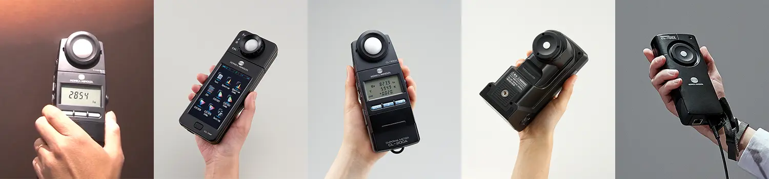
จากซ้ายไปขวา: T-10A, CL-70F, CL-200A, CL-500A และ CL-700A
- T-10A และ T-10MAเหมาะสำหรับการวัดระดับความสว่าง การกระจายแสง และการวัดหลายจุดเป็นประจำ T-10MA มีตัวรับสัญญาณขนาดกะทัดรัด เหมาะสำหรับการทดสอบที่ที่มีพื้นที่วัดจำกัด
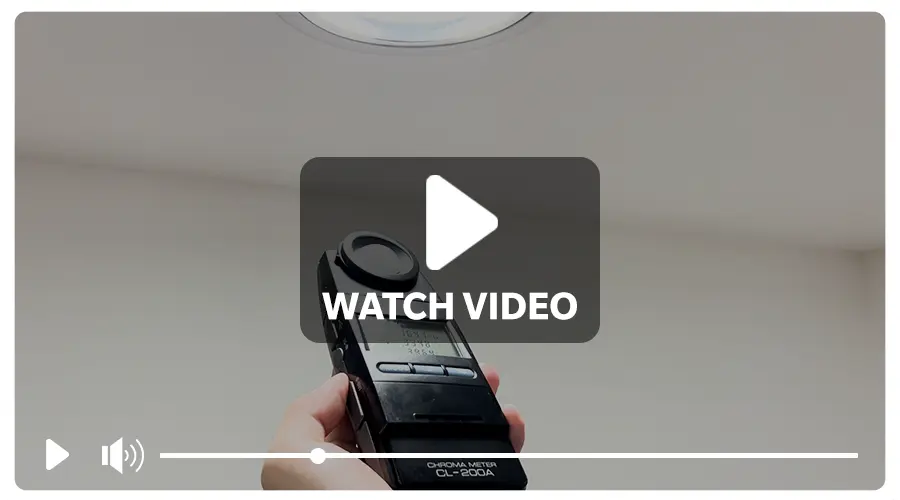
- CL-200Aเครื่องมือนี้ใช้วัดค่าความสว่าง ความเข้มสี อุณหภูมิสี และค่า Δuv เหมาะสำหรับกรณีที่ต้องการตรวจสอบทั้งระดับแสงและสีของแหล่งกำเนิดแสง โดยไม่ต้องใช้ข้อมูลสเปกตรัมแบบเต็มรูปแบบ
- CL-70Fอุปกรณ์นี้ให้การประเมินสเปกตรัมแบบพกพาสำหรับค่าความสว่าง ค่าสี อุณหภูมิสี ความเข้มของรังสีสเปกตรัม และคุณสมบัติการแสดงสี มีประโยชน์สำหรับการตรวจสอบสเปกตรัมเฉพาะจุดและการแก้ไขปัญหา
- CL-500Aเหมาะสำหรับการประเมินสเปกตรัมแสงที่มองเห็นได้และความสว่างอย่างครอบคลุมในระหว่างการติดตั้งอุปกรณ์ การทดสอบในห้องปฏิบัติการ และการวิเคราะห์แหล่งกำเนิดแสงอย่างละเอียด
- CL-700Aเป็นเครื่องวัดสเปกตรัมความสว่างขนาดกะทัดรัดที่สามารถบูรณาการเข้ากับระบบได้ ออกแบบมาสำหรับการวัดความเร็วสูง ความแม่นยำสูง และการวัดหลายจุด ช่วงความยาวคลื่นครอบคลุมไปถึงย่านอินฟราเรดใกล้ จนถึง 1,000 นาโนเมตร
รับชมวิดีโอ
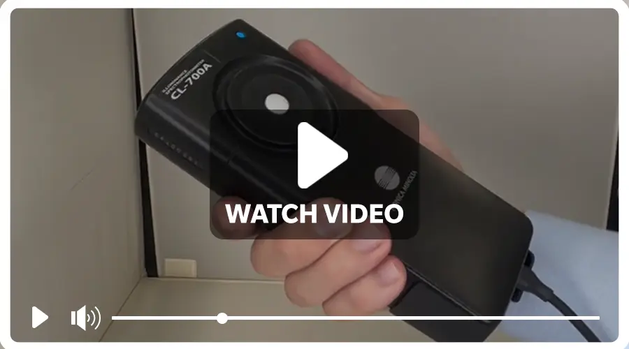
วิดีโอ CL-700A
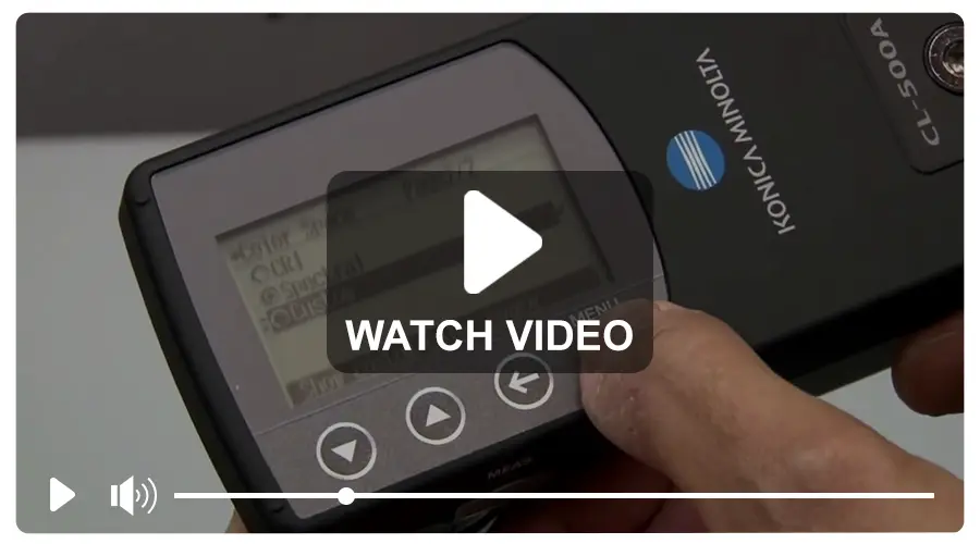
วิดีโอ CL-500A
วิดีโอ CL-200A
ขั้นตอนการตรวจสอบความถูกต้องเชิงปฏิบัติ
เพื่อให้ได้ผลลัพธ์ที่เปรียบเทียบได้อย่างมีความหมาย กระบวนการตรวจสอบความถูกต้องควรจำลองเงื่อนไขการวัดที่ใช้ระหว่างการตรวจสอบคุณสมบัติครั้งแรกของการปฏิบัติการนั้นๆ
ขั้นแรก ให้เปิดแหล่งกำเนิดแสงและรอจนกว่าจะถึงสภาวะการทำงานที่เสถียร บันทึกค่าความสว่างเป็นระยะๆ และเริ่มการตรวจสอบความถูกต้องก็ต่อเมื่อค่าที่วัดได้อยู่ในช่วงความเสถียรที่กำหนดไว้เท่านั้น
ขั้นตอนต่อไป ให้วางตัวตรวจจับไว้ที่ระนาบการวัด ระยะทาง ความสูง และทิศทางที่กำหนดไว้ ควรใช้ตัวยึดตำแหน่งหากเป็นไปได้ เนื่องจากมุมหรือตำแหน่งที่เปลี่ยนแปลงเล็กน้อยอาจส่งผลต่อผลลัพธ์ได้
วัดค่าความสว่าง ณ ตำแหน่งอ้างอิงที่กำหนดไว้ และเปรียบเทียบกับค่าพื้นฐานเดิมและค่าความคลาดเคลื่อนที่ยอมรับได้ จากนั้นกำหนดจุดตารางที่ต้องการทั่วพื้นที่ทดสอบ แล้วจึงคำนวณค่าความสม่ำเสมอโดยใช้สูตรเดียวกับที่ใช้ในระหว่างการตรวจสอบคุณสมบัติ
ในกรณีที่ต้องการวัดค่าสี ให้วัดค่าความสว่างสี (chromaticity), อุณหภูมิสี (CCT), ค่าความแตกต่างของแสงยูวี (Δuv) หรือการกระจายพลังงานสเปกตรัม ณ ตำแหน่งที่กำหนด เปรียบเทียบผลลัพธ์กับค่ามาตรฐานที่ได้รับการยอมรับ แทนที่จะพึ่งพาเฉพาะค่า CCT ที่ระบุไว้เท่านั้น
การวัดค่าซ้ำหลายๆรอบหรือตรวจค่าใหม่มีจำเป็นต่อเมื่อมีการเปิดและปิดอุปกรณ์ การทำเช่นนี้จะช่วยยืนยันว่าแหล่งกำเนิดกลับคืนสู่สภาวะเดิมอย่างสม่ำเสมอ
สุดท้าย บันทึกผลลัพธ์โดยแยกตามการทดสอบ วันที่ เวลาการทำงานของแหล่งกำเนิด และสถานะการบำรุงรักษา หากค่าใดอยู่นอกเหนือค่าความคลาดเคลื่อนที่กำหนด ให้ตรวจสอบสาเหตุที่เป็นไปได้ เช่น แหล่งกำเนิดเสื่อมสภาพตามอายุ การเปลี่ยนแปลงอุณหภูมิ ความไม่เสถียรของแหล่งจ่ายไฟ เลนส์ปนเปื้อน ความเสียหายของตัวกระจายแสง หรือการวางตำแหน่งตัวตรวจจับไม่ถูกต้อง หลังจากดำเนินการแก้ไขแล้ว ให้วัดแหล่งกำเนิดอีกครั้งก่อนนำการทดสอบ กลับไปใช้งานจริง
ค้นหาโซลูชันการวัดที่เหมาะสม
การตรวจสอบความถูกต้องอย่างสม่ำเสมอช่วยให้ผู้ผลิตระบุความคลาดเคลื่อนของทดสอบได้ก่อนที่จะนำไปสู่การปฏิเสธที่ไม่จำเป็น การยอมรับที่ไม่ถูกต้อง หรือการเปลี่ยนแปลงผลผลิตที่ไม่สามารถอธิบายได้ Konica Minolta Sensing นำเสนอเครื่องมือสำหรับการตรวจสอบความสว่าง การวัดค่าสี การประเมินสเปกตรัม และการตรวจสอบการผลิตแบบหลายจุด
ปรึกษาผู้เชี่ยวชาญด้านการวัดแสงของเราเพื่อเลือกเครื่องมือที่เหมาะสมและสร้างขั้นตอนการตรวจสอบความถูกต้องที่ใช้งานได้จริงสำหรับการทดสอบโมดูลกล้องสมาร์ทโฟนของคุณ