Radiometer
Radiometer is a device used to measure the intensity of radiant energy. A majority of radiometers use only single photocell sensors. In order to measure radiation emitted from a specific spectrum or to incorporate the radiometer within a certain spectral response, an optical filter is normally used. Such optical filtering offers a simpler and more cost effective solution.
The industrial applications of radiometer mainly involve irradiance and radiance measurement. In order to quantify the radiation emission from source, radiance measurement is normally used. On the other hand, when the level of exposure is of concern, the irradiance or the integrated irradiance measurement is then carried out.
Applications of Radiometer
Radiometer is commonly used in industry to quantify light which is outside the visible spectrum, i.e., ultraviolet and infrared. Ultraviolet (UV) light is widely used in the industry for various applications, for example,
- Curing of photoresists in semiconductor manufacturing
- Curing of emulsions for printing or plate-making
- Color-fastness testing
- Biological application
To conduct UV measurement by radiometer, either radiance or irradiance measurement, the spectral response (wavelength range and peak wavelength) should be specified to match the specific application.
Besides UV, infrared energy is also a common parameter in the field of radiometric measurement. Infrared measurement is useful as all material emits infrared radiation according to their thermal energies. Infrared thermometer utilizes the principle of infrared radiance measurement to determine the temperature of object by non-contact means. Hence, such infrared radiometer is also commonly known as “Radiation Thermometer”. Different filters with specific spectral responses are used for different applications and temperature ranges. For more details about temperature measurement by infrared detection, please refer to our publication on ‘The Wonders of Temperature’.
Photometer
A photometer can be defined as an instrument for measurement of visible light. Luminance and illuminance meters are the most common photometers and are easily available as turnkey systems. Luminous flux meters and luminous intensity meters are not widely available and usually have to be customized to the specific light measurement application due to the geometry of measurement involved.
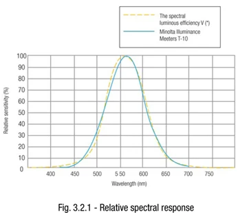
The basic difference between radiometer and photometer, is that the latter must respond to light as the CIE standard observer. In other words, the spectral response of the photometer must follow the CIE Standard Luminosity Function V*curve.
Sensors
The sensor of the photometer, which decides the conformity to the CIE V* curve, is critical to the accurate performance of the photometer. Non-filtered and filtered sensors have been used in photometers.
Non-filtered sensors, such as the selenium and cadmium sulfide, inherit a natural spectral response which approximate the V* curve. However, its deviation from the V* curve makes it impractical for accurate photometry measurement and it is more commonly used in automatic light switches applications. Most modern filtered photometers use silicon photo diodes which incorporate optical filters in front of the sensor so that the transmission of the filter and the spectral response of the sensor can be combined to closely match the CIE V* curve.
CIE recognized the need for a meaningful and internationally applicable method of specifying the quality of a photometric sensor. Hence, f1 value is developed for this purpose. The f1 value, specified in percentage error, represents the degree to which the relative spectral responsivity matches CIE V* curve.
Calibration Method
Beside f1 value, the calibration method of the photometer is also an important factor when deciding its suitability to a specific application. For example, a photometer with a relative large f1 value can still achieve good accuracy when the measured light source and the standard lamp used during the calibration process is similar. There are two basic methods of calibrating photometers. The first and the most common method is using a standard lamp (usually tungsten lamp). These lamps are certified and traceable to national standard laboratories/institutions. The photometers will be adjusted until the measurement reading matches the certified output of the standard lamp. The second calibration method is to use standard detectors. Such detectors have built-in sensors where the spectral responses perfectly match the CIE V* curve. In such calibrations, a lamp is still required but output can be varied but must be stable. The standard detector first measures the output of the lamp, and is substituted by the photometer and will be adjusted until the measurement give similar readings as the standard detector. Such detectors can also be certified and traceable to national standards.
Color Correction Factor
The correction of the detector-filter combination to the CIE V* curve is generally poor at the end of the visible spectral range. Hence, the color temperature of the lamp used during calibration is critical. As most of the photometers are calibrated by a tungsten lamp, measurement of incandescent, halogen searchlights and sunlight generally give good accuracy. However, these photometers are not suitable for measurement of monochromatic light or narrowband emitters, e.g., blue and white LEDs. Measurement error will also be significant in discharge lamps, e.g., luminescent tubes, which show clear peaks (i.e. spectral lines) in the visible spectrum.
For this reason, modern photometers have incorporated a Color Correction Factor feature to compensate the error caused by this spectral response difference between the sensor and the CIE V* curve. The CCF value can be calculated when both the spectral response of the sensor and the spectral power distribution of the light source is known. An alternate and easier method is to transfer the measurement data of a primary standard (for example, data taken from a spectroradiometer) to the photometer is by varying the CCF value. CCF can also be used as a user-calibration feature, which is particularly useful if in-house standards’ traceability is necessary.
Applications of Photometers
There are a multitude of light measurements to be made. Not surprisingly, misapplication of photometric instrument by user can become a common source of error. For many users, the main obstacle to effective light measurement is the lack of understanding of the characteristics of the type of measurement required. Attempts to convert between units will lead to gross errors. For example, the most common mistake encountered is attempting to use illuminance meter (lumen/m2) to determine luminous flux (lumen), or, to use luminance meter (candela/m2) to determine the luminous intensity (candela).There are four main photometric instruments, namely the luminance meter, illuminance meter, luminous flux meter,and luminous intensity meter.

